这是tessent官方提供的一个层次化的example,路径在${tessent_install_dir}/share/UsageExamples。
最上层是top,top下面有gps_baseband和processor_core两个block,其中gps_baseband是没有memory的,processor_core含有memory,需要做mbist。
basic concept
DFT Two Pass Flow:
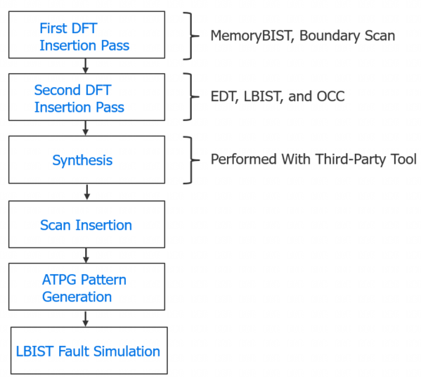
首先进行MBIST和Boundary Scan,这一步的操作对象通常是RTL;第二步插入EDT和OCC,第一步插入的逻辑也会被EDT测试。图1-2是一个待插入的Design。
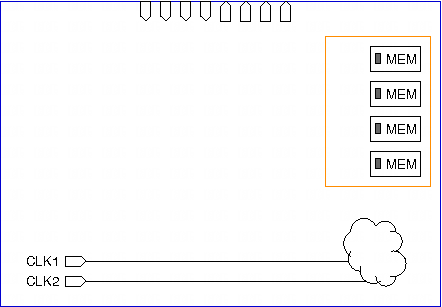
图1-3是插入MBIST和Boundary Scan后的示意图。
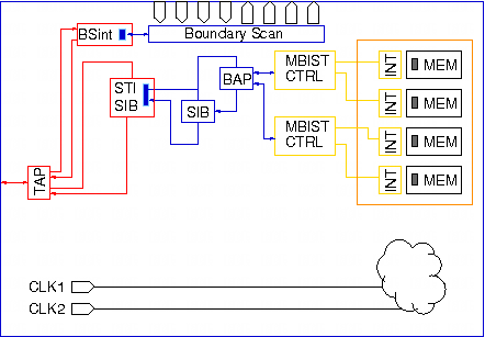
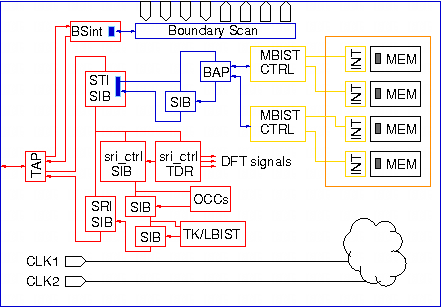
图1-4是插完EDT和OCC的示意图。
两步流程的第一步具体在tshell上的流程如下:
- Load design
- set_context -deign_id
- set tsdb out
- read libraries
- read design
- elaborate design
- set_dft_specification_requirements
- set_design_level
- set_attribute_value 映射 ijtag pin
- check_design_rules
- create_dft_specification
- process_dft_specification、extract_icl
- create_patterns_specification
第二步流程基本类似:
- Load design
- set_dft_specification_requirements
- create_dft_specification
- generate EDT、LBIST and OCC hardware
- Extract ICL Module Descriptions
- Generate ICL Pattern
需要注意的是,第二步load dedsign的过程中需要指定一个新的design ID,并且使用同一个tsdb out文件夹,并且需要读取第一步输出的design并elaborate。
通常design ID的命名习惯为:rtl1为第一步、rtl2为第二步、gate为scan chain insertion。
在输出的tsdb中,包含了每个design ID关联的步骤的所有数据,由于rtl2步骤是增量的, 它也包含必要的rtl1的数据。在后续的步骤中,可以使用design ID来load此前的design,也可以手动指定必要的design文件。
processor_core flow
- insert_mbist
- insert_edt_occ
- synthesize_rtl
- insert_scan
- generate_atpg_patterns
- validate_mbist_gate_level
- generate_atpg_patterns_post_layout
1. insert_mbist
运行run_mbist_insertion脚本,内容如下:
#! /bin/sh -f
#\
exec tessent -shell -log logfiles/$0.log -replace -dofile "$0"
首先这是一个shell脚本,exec这条命令会调起tessent shell重新执行这个脚本(执行后续的tcl命令),这种 “polyglot”(多语言)脚本 技巧在 Tcl/Shell 组合中很常见。
Note:
Shell 阶段:exec替换进程,进入tessent。
Tcl 阶段:#\和下一行被合并成#exec ...,变成 Tcl 注释,因此tessent不会重复执行exec。
# Set the context to insert DFT into RTL-level design
set_context dft -rtl -design_id rtl1
每次运行tshell,都需要指定一个context,不同的context对应不同的点工具,这里使用dft,表示要进行dft插入。
-rtl表示当前的dft插入操作在rtl代码上进行,与之对应的还有-no_rtl,表示在网表上进行dft插入。
-design_id可以用户自定义一个字符串,当需要两步insertion时(mbist和edt_occ),需要指定不同的design_id,如果仅做一步insertion(无mbist),则可不用指定,在-rtl时,默认id为rtl,在-no_rtl时,默认id为gate。
# Set the location of TSDB. Default is at the current working directory
set_tsdb_output_directory ../tsdb_outdir设置tsdb的路径,tsdb是tshell的database,保存了一些dft流程中的生成的配置文件和输出文件,这些文件在后续流程中可以通过open_tsdb命令进行重用。
# Read cell library
read_cell_library ../../../library/standard_cells/tessent/adk.tcelllib
读取cell library,cell library包含两部分,dft_cell_selection字段和各个cell model的定义。
model定义通常对应工艺库(tsmc)中以mdt为结尾的文件,dft_cell_selection需要手动编写。
# Read the memory library model
set_design_sources -format tcd_memory -y ../../../library/memories -extension tcd_memory
读取指定文件夹下的tcd_memory后缀的文件,该文件描述memory的规模布局、接口信息、读写行为以及测试算法等等。
# Read memory verilog model
read_verilog ../../../library/memories/*.v -exclude_from_file_dictionary
读取memory的verilog model,-exclude_from_file_dictionary选项表示不作为DC综合的输入。
# Read the design
read_verilog -f rtl_file_list
读取design的filelist。
set_current_design processor_core设置当前design的顶层。
# Set the design level as physical_block
set_design_level physical_block
为了能够进行bottom_up和平行化设计,将大的design分成小的block,在tessent工具视角,将需要进行DFT的design分成多个level,主要有sub_block、physical_block和chip。chip中包含了多个physical_block和sub_block,physical_block中也可能包含多个physical_block和sub_block。
physcal_block是逻辑实体,具有单独的SDC,能够被独立综合和signoff。
sub_block的SDC包含在其所在physical_block或者chip的SDC中,只能和其所在physical_block或者chip一起综合,综合后有可能被flatten,不能产生独立的netlist。
因此,sub_block不能独立参与scan flow,而是在其所在physcial_block或者chip进行scan_insertion时完成scan design。
chip相比于physical_block在scan阶段最大区别在于要进行boundary scan。
# Specify DFT requirements to insert memory test
set_dft_specification_requirements -memory_test on
当memory_test开启时,memory_bist、memory_bisr_chains和memory_bisr_controller默认为auto;否则,它们默认为关闭。
# Specify the clocks feeding memories
add_clocks 0 dco_clk -period 3.0ns
时钟是必须要指定的,drc检查需要根据时钟信息trace sram的时钟通路是否正常,在生成mbist pattern时也需要生成对应频率的时钟,这里0表示关闭状态下默认为0,dco_clk为port name。
check_design_rules执行drc检查。
report_memory_instances打印memory信息。
# Create and report DFT Specfication that can be modified if necessary
set spec [create_dft_specification]
report_config_data $spec
创建dft spec并打印,必要时可以编辑。
# Generate and insert the hardware
process_dft_specification
执行dft插入。
# Extract IJTAG network and create ICL file for the design
extract_icl
提取icl,icl全称为Instrument Connectivity Language,包含了所有组成当前design的instrument access network,以及这些instruments之间的逻辑连线信息
# Generate patterns to verify the inserted DFT logic
create_pattern_specification
process_pattern_specification
生成mbist pattern。
set_simulation_library_sources -v ../../../library/standard_cells/verilog/adk.v -v ../../../library/memories/*.v
# Point to the libraries and run the simulation
run_testbench_simulations
运行仿真,这里默认调用的mentor的QuestaSim仿真工具。
我们通常使用VCS仿真,需要修改一下脚本,在create_pattern_specification之前输出一个用于DC综合的post dft的rtl导入文件:
...

# Generate post dft rtl file list for VCS simulation
write_design_import_script processor_core.dc_design_load_script -replace
exec bash ./gen_post_dft_flist processor_core.dc_design_load_script

# Generate patterns to verify the inserted DFT logic
create_pattern_specification
process_pattern_specification

...
write_design_import_script 这条命令用于输出一个用于DC综合的file list文件,我们编写一个脚本gen_post_dft_flist,用于提取其中的文件名,生成一个用于VCS仿真的file list。
gen_post_dft_flist脚本内容如下:
#!/bin/bash

# 输出文件名
output_file="post_dft.f"

# 清空或创建输出文件
> "$output_file"

# 添加头部信息
{
    echo "// Post dft rtl file list generate by script $0"
    echo "// Generated on: $(date)"
    echo "// User: $(whoami)"
    echo "// Hostname: $(hostname)"
    echo ""
} >> "$output_file"

# 提取所有双引号之间的内容并写入输出文件
grep -o '"[^"]*"' $1 | sed 's/"//g' | while read -r line; do
    echo "$line" >> "$output_file"
done

echo "User script: extract post dft rtl file list to $output_file."最后,编写一个用于VCS仿真的脚本,run_sim:
#!/bin/bash
PATT=MemoryBist_P1
DESIGN=processor_core

mkdir -p ${DESIGN}_${DUT}/${PATT}
mkdir -p ${DESIGN}_${DUT}/${PATT}/logfiles
cd ${DESIGN}_${DUT}/${PATT}

find ../../../tsdb_outdir/instruments/ -name "*.v" | xargs realpath > instrument.f

vcs -full64 -lca -kdb +plusarg_save +acc -debug_all -debug_access-memcbk +warn=noIUWI -error=noMPD -sverilog \
	-ucli -R -o ${PATT}.simv -i ../../ucli_cmd.tcl \
    -timescale=1ns/1ps \
	-l ./logfiles/${PATT}.log \
    -v /project/flow/dft/tessent_example_hierarchical_flow_v2023.1/library/standard_cells/verilog/adk.v \
    -v /project/flow/dft/tessent_example_hierarchical_flow_v2023.1/library/memories/SYNC_1RW_8Kx16.v \
    +incdir+/project/flow/dft/tessent_example_hierarchical_flow_v2023.1/wrapped_cores/processor_core/rtl \
    -f ../../post_dft.f \
	../../../tsdb_outdir/patterns/${DESIGN}_rtl1.patterns_signoff/${PATT}.v \
    +NEWPATH="../../../tsdb_outdir/patterns/${DESIGN}_rtl1.patterns_signoff" \
	-top TB

cd ../../
再搭配一个用于仿真控制的ucli命令脚本,ucli_cmd.tcl:
dump -file "wave.fsdb" -type FSDB
dump -add .
run依次运行run_mbist_insertion、run_sim,可以看到仿真结果:
Simulation finished at time 42701
Number of miscompares            =           0
Number of 0/1 compares           =         170
Number of Z compares             =           0
好